
To kick off 2014, I am streamlining my live gigging rig. The 2 keyboards (Roland Fantom G7 and Korg Kronos 73) will remain the same, but I am completely changing my stage monitoring setup. For several years I have used a small Soundcraft Compact 10 mixer feeding into a 225W+225W stereo power amp feeding a pair of ABS shell 250W floor wedges. It’s a great setup, but it is LARGE and can make setup a bit of a squeeze when we are on a small stage. To this end, I am swapping my current setup for an HK Lucas Nano 300 (http://hkaudio.com/Lucas_nano/info.php). It is a very compact system, but the mixer section comprises of 1 mono mic channel, 1 stereo balanced line input and 1 stereo unbalanced line input. Since I have 2 stereo balanced line keyboards, I’m going to need to do some sub-mixing.
")
Balanced line mixer circuit (© Rane Corp)
I considered using a small compact mixer, but soon decided all I was doing was adding more and more level controls and gain stages where they are simply not necessary. Given the current vogue for “Summing mixers”, it dawned on me that all I needed was a passive balanced stereo line mixer. Some thorough Googling soon unearthed a suitable circuit schematic, courtesy of Rane Corporation (http://www.rane.com/note109.html). Adapting it for stereo use requires nothing more than building the circuit twice, once for the left and once for the right channel.
Required components
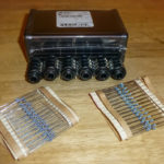
More Googling found a suitable robust case, the Hammond 1455K1201BK which conveniently has a removable “belly panel” which made assembly and wiring of the mixer circuit a much easier task. The case would probably just about accommodate 3 stereo inputs and a stereo output, but I’ve opted for just the 2 stereo inputs that I need. The other components are simply 2x 20kΩ 1% resistors, 4x 470Ω 1% resistors per stereo input channel (8 in total in this case), 2 stereo jack sockets for the outputs and 2 stereo jack sockets per input channel (4 in total in this case).
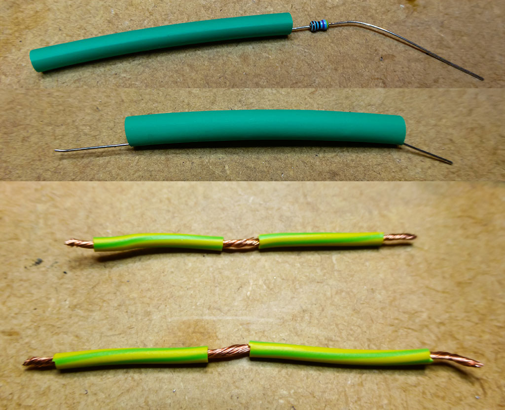
Resistors and links
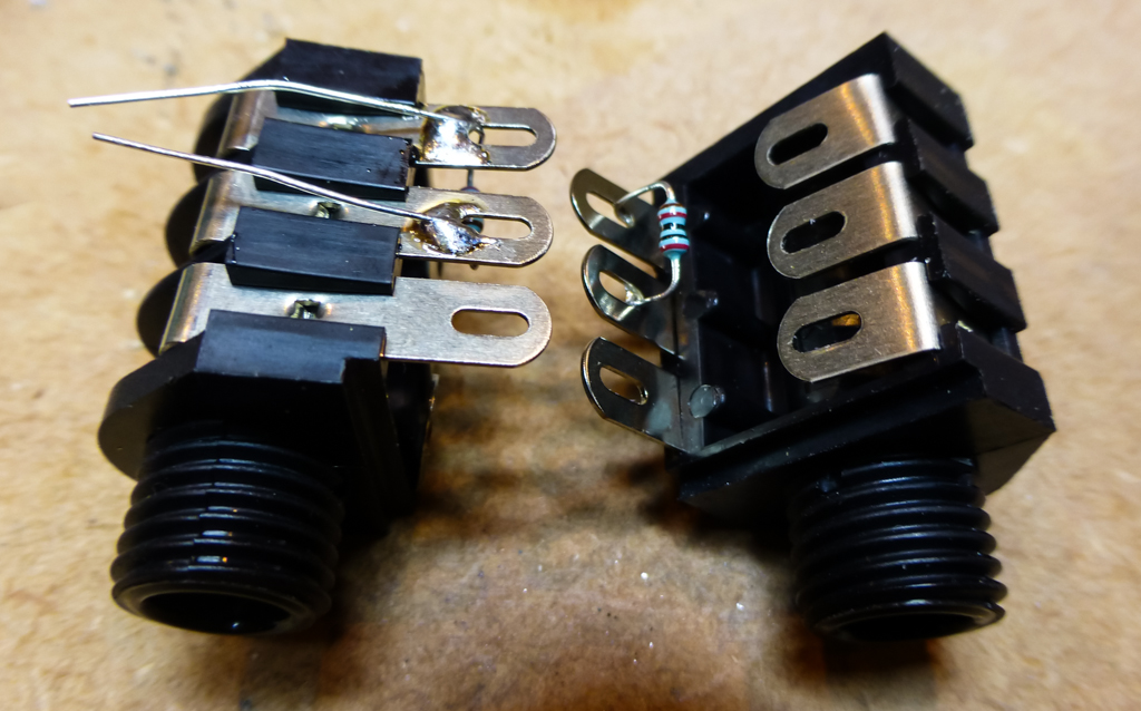
Output socket resistor
With all the components sourced, a few preparation steps can be done before assembly. First, insert 2 of the 470Ω resistors into some fairly snug heatshrink tubing. This will ensure the bare leads do not short the circuit anywhere as they are routed past and adjacent channel input socket. Prepare a bare ends and a bare middle section to 2 lengths of hookup wire which will connect together the common earths of each channel. It is also a good time to preinstall and solder the 20kΩ resistors between the hot and cold terminals of the balanced output socket
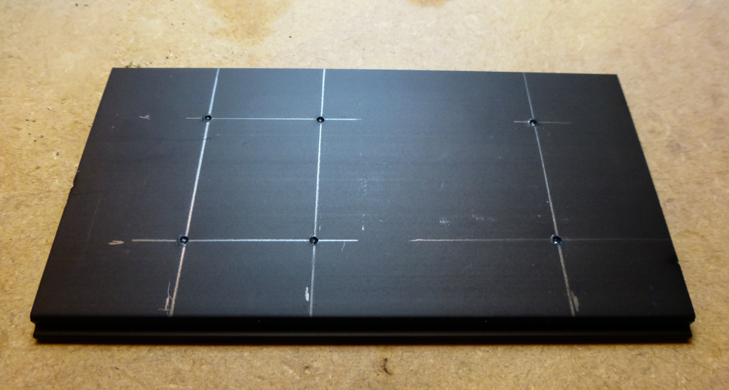
Centre punch each location
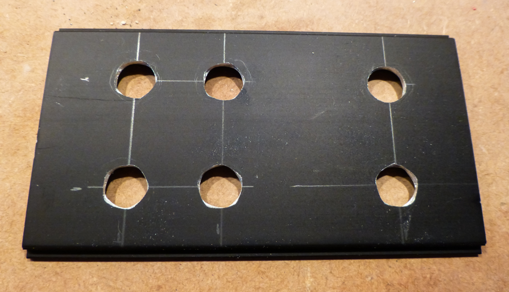
Full 11mm holes
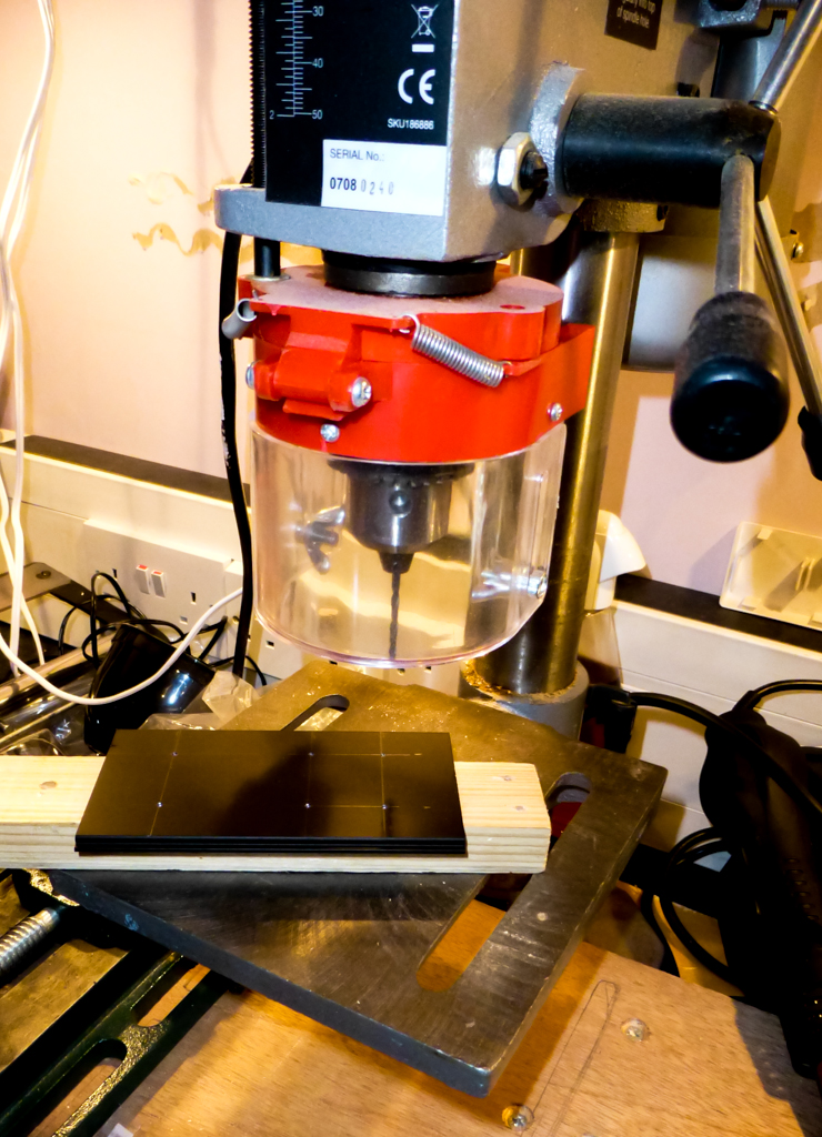
Use a pillar drill
The next item to prepare is the metalwork. Six 11mm holes are required to mount the input and output channel sockets in the “belly panel”. First of all, carefully mark out and then centre-punch each socket position. If you have one, I strongly advise using a pillar-drill to drill and casework holes. Pre-dill pilots holes with a smallish 3mm or so drill bit, and then enlarge the pilot holes using an 11mm drill bit.
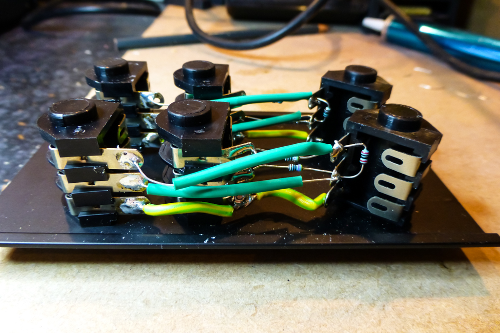
Wiring completed
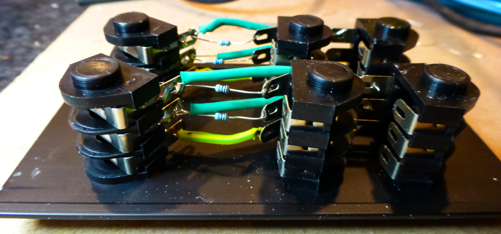
Rear view
With the preparation done, the sockets can be installed in the belly panel, the ground link wires soldered in place, then install and solder the 470Ω resistors between the input and output sockets, using the heatshrink shrouded resistors to connect the input sockets furthest away from the output sockets. take care not to breach the heatshrink around the resistors as it is there to prevent any short circuits where the resistor leads route around the other input sockets.
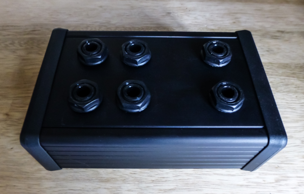
Passive mixer completed
Finally, check the wiring using a multimeter to measure the resistance between various combinations of the input and output socket terminals. Once all connections are confirms, it is time to reassemble the case and install the rubber feet.
Trackbacks/Pingbacks