
I’ve finally made a start on building a passive monitor controller. I’ve had a good look at the various options available on the market and decided that I can build the kind of spec I’m looking for much cheaper than I can buy one.
It will have 4 selectable inputs, where the selected one can be routed to 4 selectable outputs. In the middle of this routing is a volume control. I’ve opted for a stereo balanced motorised ALPS attenuator with remote control. I’m modifying some Chinese kits I bought from eBay and intend to change the original design to allow the use of illuminated push buttons for channel selection as opposed to the default rotary switch design.
The only parts I’m currently left to source are a nice 2U shallow depth chassis (the 1U I originally bought won’t be tall enough!) a big knob (ohhhh Matron!) and a suitable toroidal 240/12-0-12 transformer for the PSU.
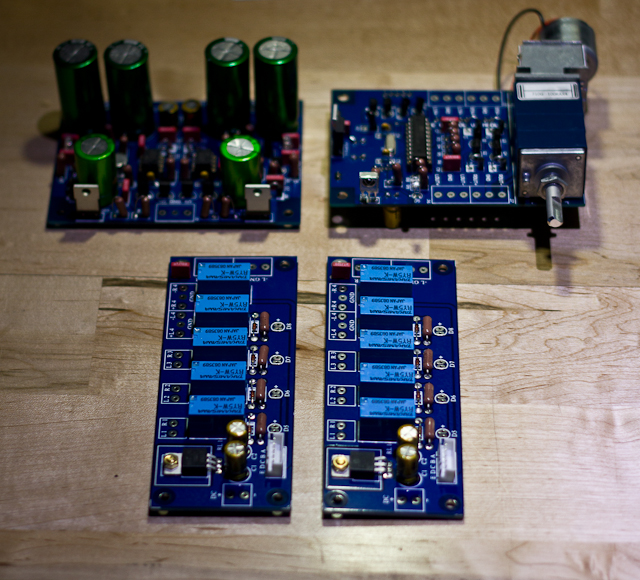
The project consists of 4 PCBs:
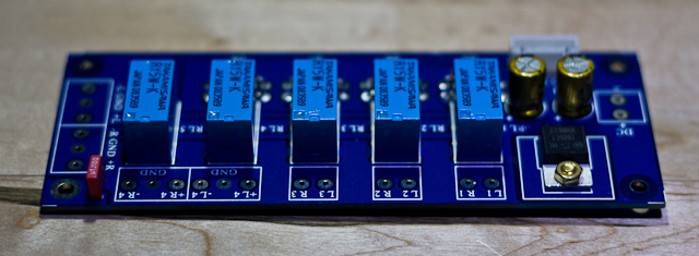
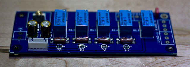
- 2 selector boards employing relays to switch the audio path, one is for input sources, the other for output destinations.
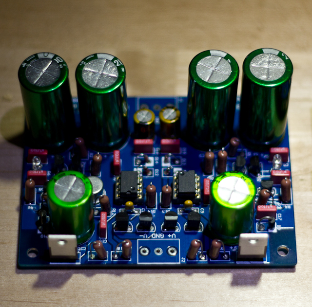
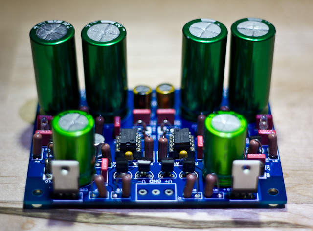
- Voltage regulator board, set for 12v – 0 -12v. This will be fed by the above mentioned transformer.
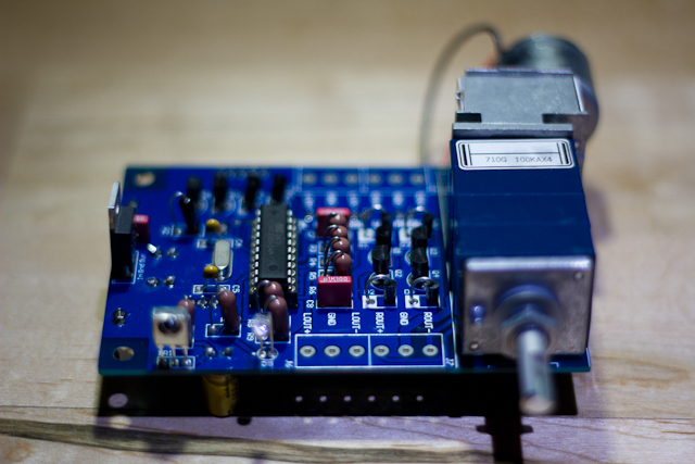
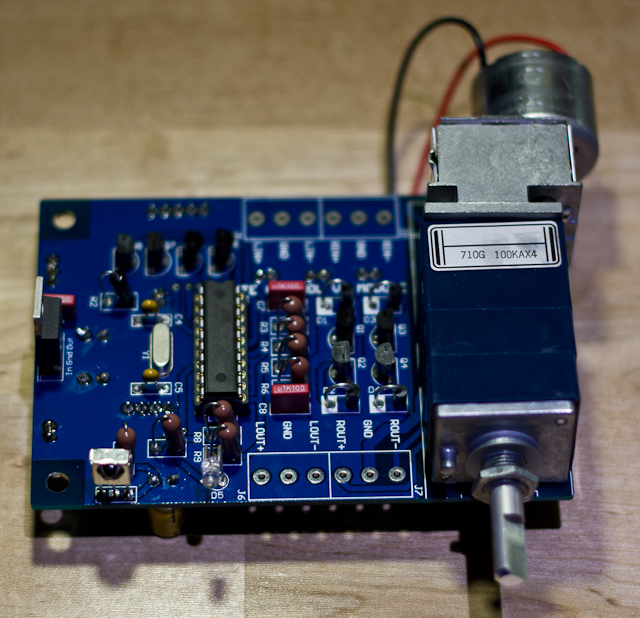
- IR remote control attenuator board which has the ALPS motorised fader mounted on board.
I’ve taken this opportunity to make use of my new camera (Canon EOS 550D) and have shot HD footage of me assembling the first PCB (the input selector board) demonstrating how I prepare components, mount them on the board, solder them and finally trim the leads. The video is below followed by a selection of photos of the 4 finished boards. I’ll post more as I move through the assembly process.
Just as a little note, I had to colour-correct the video and I’m not quite happy with the resulting colour cast. I did have the perfect temperature lighting for this (see the photos), but it was partly supplied by mains LED lighting and it was strobing when being filmed! I had to use a halogen bulb instead but the colour temperature was way too low giving a heavy yellow colour cast.
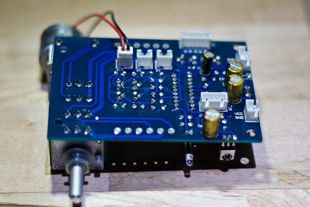
and now the photos:
Recent Comments