
I’ve spent the last few months building a new MIDI control surface specifically for controlling EQ plugins. It was an idea I had last year. I actually pitched the idea to Novation, along with a mocked up image of what it could look like as I thought their rotary encoders with the LED rings along with their Automap software would make for an impressive package. Sadly, it seems they filed it under “R”. That left me with my only option – build one myself.
Having spent sometime researching what MIDI controllers, kits and pre-built modules are available, I finally settled on a neat little board from a US company called Hale Micro Systems. I bought one of their UMC32 modules. Essentially it’s a converter board that takes 32 digital or analog inputs and converts them to MIDI messages which are transmitted over a USB connection using your OSs built-in class-compliant drivers.
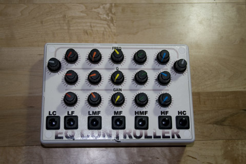
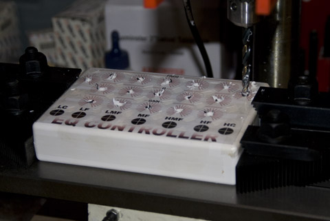
To cover the majority of EQ plugins, but primarily the UAD Cambridge (and due to the fact that it emulates the Sony Oxford EQ, it also applies to the Sonnox R3 EQ plugin which I also use), my design would need controls for 5 parametric bands with Freq, Gain, Q pots and an Enable switch plus a Freq pot and Enable switch for both High cut and Low cut filters. In terms of aesthetics, I also wanted to echo the colour-coding of the controls which meant endless Googling of potentiometer knobs on an endless stream of component manufacturer websites.
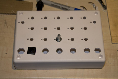
Having found the pots, switches and knobs I was going to use, I was then able to design the layout and therefore choose a suitably sized case for the project. The front panel legend was made up in CorelDraw. I printed a copy on normal paper and taped it to the top of thew case and used it as a drilling guide. Once the drilling was completed, the legend was printed onto water-slide decal paper, and then after soaking in water was transferred onto the prepared case. After drying overnight it was then coated with several layers of clear matt acrylic lacquer.
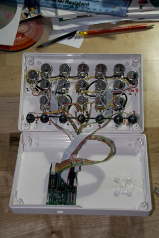
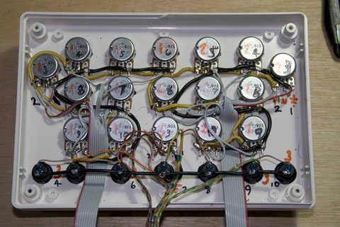
The next job was to wire up the pots and switches. All were connected to a common ground and +5v supply from the UMC32, then the middle wiper of each pot and opposite terminal of each switch was wired in turn to 24 of the UMC32’s inputs.The UMC32 itself was then stuck to the inside of the case simply by using double sided sticky foam pads so that the Mini-USB socket protruded into a pre-drilled hole allowing the unit to be plugged into a standard USB port on my PC. Using the UMC32’s config application, each channel was configured as a digital switch or analog input and assigned to specific MIDI continuous controller numbers.
Hi I’ve been thinking of building a similar controller using the UMC 32+ for ableton. I wanted to know where you got that case.
Any help would be greatly appreciated.
thanks
Abe
I got it from CPC (great online retailer for components): MultiComp EN81845 ABS case
Sweet thanks!!!!
Hi!
Can I order this nice piece of gear from you?
regards
Florian
Hi Florian, sorry, but I’m not building these commerially or for resale. However, they are not difficult to build, why not have a go yourself?
I think is so interesting all you can to do with virtual instruments and midi interfaces, really fascinating, so I dedicate most of my time searching for new information on all such musical things that are technically very important and all the work composition. Very good post very informative,I will keep checking this blog `cause I found it very interesting, thank you very much, greetings to all, bye
I always spent my half an hour to read this weblog’s posts all the time along with a cup of coffee.
This is a fantastic piece of work! I wish somebody would make this. I want it badly enough that I’m toying with the idea of going the DIY route. Great to see you’ve had success.
Hi Glenn. I realise this is replying to a three year old comment, but wanted to mention that since this project was completed, it seems Softube came up with the same idea I had for a series of these controllers combined into a channel strip: the Softube Console One.
hey. does it work with pro tools and eq band 7?
Assuming you mean the 7-band ProTools EQ3, I guess it should do, though probably only the Freq parameter of the HPF and LPF bands would be controllable as my controller only has one knob for the high and low pass bands.